A few weeks ago Nik Player told us about his modifications he did on the AC15HW. Because of the fact that the AC30HW and the AC15HW ist nearly the same, I tried his mods at this amp and I really can recommend them. So below you see his mods described and adapted for the AC30HW. Original article of Nik Player is available in his blog.
WARNING - These amps contain lethal high voltages which can remain present even when the amp is unplugged from the mains supply, do not attempt any modifications unless you know what you are doing.
Made changes:
- Reducing the DC filtering capacitor values and using better quality caps.
- Changing to better quality signal capacitors.
- Adding grid stoppers to the Top Boost and Phase Inverter to avoid blocking distortion.
- Reducing (or even shortcut) R17 to give more gain in the Normal channel.
These simple changes really liven up the amp and remove some the modern "stiffness" associated with too much DC filtering.
All components should be replaced with voltage ratings no less than the originals.
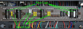
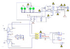
Signal Cap Changes:
C13 - Silver Mica 220pF (Bright Switch Cap)
C22 - Silver Mica 100pF (TB Bright Cap)
C21 - Silver Mica 500pF (TB coupling cap)
C23 - Silver Mica 47pF (Treble Cap)
C24 - Mallory 22nF (Middle Cap)
C25 - Mallory 22nF (Bass Cap)
C7, C10, C12, C14, C27 - Mallory 47nF (Stage Coupling Caps original values 100nF)
Filter Cap Changes:
C1 - F&T 500v 22uF
C2 - F&T 500v 22uF (original value 47uF)
C3, C4 - 630v 100nF (original values 10nF)
C5, C6 - F&T 500v 10uF (original values 47uF)
C19 - F&T 500v 30uF (original value 47uF)
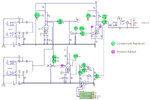
Resistor Changes:
R17 reduced from 330K to 160K or even shortcut for maximum gain (neccessary if you want that Brian May playing style)
Add 7.5K 27K resistors to the input pins 2 & 7 of v2 Phase Inverter
Add 7.5K 27K resistor to the input pin 2 of v9 TB channel
I have tested 27K grid stoppers with no detrimental effects to high frequency roll off and these have helped smooth the break-up when the amp starts to overdrive so I would recommend them over the 7.5K.
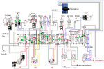
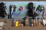
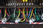
I used 500V Silver Mica for the small signal caps, 630v Mallory 150M caps for the larger signal caps and 500V F&T caps for the filtering. Resistors are all 1/2 watt. The grid stoppers are soldered directly between the tube base pin and its associated connecting wire. Click on the images below for larger versions, I have highlighted the changes with green and magenta circles.
Pictures and schematics are from AC15HW original from Nik Player´s blog. Position and changed components are the same as on the AC30HW.
Original mod by Nik Player, adapted by Jens Winkler
WARNING - These amps contain lethal high voltages which can remain present even when the amp is unplugged from the mains supply, do not attempt any modifications unless you know what you are doing.
Made changes:
- Reducing the DC filtering capacitor values and using better quality caps.
- Changing to better quality signal capacitors.
- Adding grid stoppers to the Top Boost and Phase Inverter to avoid blocking distortion.
- Reducing (or even shortcut) R17 to give more gain in the Normal channel.
These simple changes really liven up the amp and remove some the modern "stiffness" associated with too much DC filtering.
All components should be replaced with voltage ratings no less than the originals.
Signal Cap Changes:
C13 - Silver Mica 220pF (Bright Switch Cap)
C22 - Silver Mica 100pF (TB Bright Cap)
C21 - Silver Mica 500pF (TB coupling cap)
C23 - Silver Mica 47pF (Treble Cap)
C24 - Mallory 22nF (Middle Cap)
C25 - Mallory 22nF (Bass Cap)
C7, C10, C12, C14, C27 - Mallory 47nF (Stage Coupling Caps original values 100nF)
Filter Cap Changes:
C1 - F&T 500v 22uF
C2 - F&T 500v 22uF (original value 47uF)
C3, C4 - 630v 100nF (original values 10nF)
C5, C6 - F&T 500v 10uF (original values 47uF)
C19 - F&T 500v 30uF (original value 47uF)
Resistor Changes:
R17 reduced from 330K to 160K or even shortcut for maximum gain (neccessary if you want that Brian May playing style)
Add 7.5K 27K resistors to the input pins 2 & 7 of v2 Phase Inverter
Add 7.5K 27K resistor to the input pin 2 of v9 TB channel
I have tested 27K grid stoppers with no detrimental effects to high frequency roll off and these have helped smooth the break-up when the amp starts to overdrive so I would recommend them over the 7.5K.
I used 500V Silver Mica for the small signal caps, 630v Mallory 150M caps for the larger signal caps and 500V F&T caps for the filtering. Resistors are all 1/2 watt. The grid stoppers are soldered directly between the tube base pin and its associated connecting wire. Click on the images below for larger versions, I have highlighted the changes with green and magenta circles.
Pictures and schematics are from AC15HW original from Nik Player´s blog. Position and changed components are the same as on the AC30HW.
Original mod by Nik Player, adapted by Jens Winkler
Anhänge
Zuletzt bearbeitet von einem Moderator:
